Reset (Process)

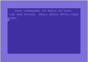
Reset refers to the process of returning the computer to the apparent default (or ground) state of the computer – with or without memory intact. The computer will return to the default start-up screen if the motherboard has not been damaged, modified or expanded.
Types[edit | edit source]
Hard Reset[edit | edit source]
Also known as a cold reset or cold start, the motherboard loses power during the reset and so the memory storage is lost. A hard reset generally occurs when the computer is turned-off. There is no reason to conduct a hard reset unless a soft reset cannot be performed, or devices are to be added to the user I/O ports and power must be eliminated before safe connection.
Soft Reset[edit | edit source]
Also known as a warm reset or warm start, the motherboard does not lose power during the reset process and so the memory storage remains intact. A soft reset can be achieved through software or hardware. Using UNNEW will re-enable any BASIC program listing residing in memory.
Memory Addresses[edit | edit source]
The reset vector tells the CPU where to find the system reset routine. The address of this routine is stored in low byte then high byte order. For all MOS Technology 65XX CPUs, the system reset vector is stored at the same address. Table 1 shows the address details for some Commodore CPUs[1].
| Table 1 - Reset Vector and Reset Routine Addresses | |||||
|---|---|---|---|---|---|
| CPU | Computer | Reset Vector Address | Reset Routine Address | ||
| Hex | Dec | Hex | Dec | ||
| MOS Technology 6502 | PET 200x | $FFFC | 65532 | $FD38 | 64824 |
| MOS Technology 6502 | CBM 300x | $FFFC | 65532 | $FCD1 | 64721 |
| MOS Technology 6502 | PET 400x, CBM 800x, SuperPET 900x | $FFFC | 65532 | $FD16 | 64790 |
| MOS Technology 6502 | CBM 500 | $FFFC | 65532 | $F99E | 63902 |
| MOS Technology 6502 | CBM 600/700 | $FFFC | 65532 | $F997 | 63895 |
| MOS Technology 6502 | VIC-20 | $FFFC | 65532 | $FD22 | 64802 |
| MOS Technology 6510 | C64, SX-64 | $FFFC | 65532 | $FCE2 | 64738 |
| MOS Technology 7501 | C16, C116, Plus/4 | $E477 | 58487 | $FF6F | 65380 |
| MOS Technology 8501 | C16, C116, Plus/4 | $8FFC | 36860 | $FF6F | 65380 |
| MOS Technology 8502 | C128x | $FFF8 | 65528 | $FF3D | 65341 |
Method of Activation[edit | edit source]

Software Activated[edit | edit source]
A reset can be achieved by using the commands JMP (machine code) followed by the hexadecimal address or SYS (BASIC) followed by the decimal address of the system reset routine. These commands will then activate the routine located at the address pointed to by the reset vector. For example, to reset the C64 from BASIC use SYS 64738.
Hardware Activated[edit | edit source]
Main article Reset Button
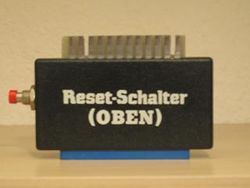
NMI and RES are triggered by an NE556 timer chip (NMI by timer A and RES by timer B) upon startup (the latter with a slight delay to ensure all ICs are supplied with proper voltages)[2]. As both the user I/O port and the serial port are directly linked to pin 40 of the CPU on 65xx, 75XX and 85XX CPUs, a reset button can be easily manufactured and fitted to activate the function from either port. There is also a RES on the cartridge expansion slot (pin C) which is utilised by many copying and editing cartridges such as Freeze Frame, Action Replay and Final Cartridge III.
Mechanics[edit | edit source]
Example Code[edit | edit source]
Commodore 64 Code[edit | edit source]
This is the default machine code routine to reset the C64:
; MOS 6510 System Reset routine[3]
; Reset vector (Kernal address $FFFC) points here.
;
; If cartridge is detected then cartridge cold start routine is activated.
; If no cartridge is detected then I/O and memory are initialised and BASIC cold start routine is activated.

FCE2   A2 FF      LDX #$FF        ;
FCE4   78         SEI             ; set interrupt disable
FCE5   9A         TXS             ; transfer .X to stack
FCE6   D8         CLD             ; clear decimal flag
FCE7   20 02 FD   JSR $FD02       ; check for cart
FCEA   D0 03      BNE $FCEF       ; .Z=0? then no cart detected
FCEC   6C 00 80   JMP ($8000)     ; direct to cartridge cold start via vector
FCEF   8E 16 D0   STX $D016       ; sets bit 5 (MCM) off, bit 3 (38 cols) off
FCF2   20 A3 FD   JSR $FDA3       ; initialise I/O
FCF5   20 50 FD   JSR $FD50       ; initialise memory
FCF8   20 15 FD   JSR $FD15       ; set I/O vectors ($0314..$0333) to kernal defaults
FCFB   20 5B FF   JSR $FF5B       ; more initialising... mostly set system IRQ to correct value and start
FCFE   58         CLI             ; clear interrupt flag
FCFF   6C 00 A0   JMP ($A000)     ; direct to BASIC cold start via vector
Post-Reset Cycles[edit | edit source]
Immediately following a reset, the first nine cycles of the MOS Technology 6502 CPU time [4] are shown in Table 2.
| Table 2 - Reset Mechanics | ||
|---|---|---|
| Cycle | Process Register | Remarks |
| #0 | AB:00FF D:00 R/W:1 PC:00FF A:AA X:00 Y:00 SP:00 P:02 IR:00 READ $00FF = $00 |
When a 6502 is turned on, the stack pointer is initialized with zero. The BRK/IRQ/NMI/RES sequence pulls the instruction register (IR) to 0. |
| #1 | AB:00FF D:00 R/W:1 PC:00FF A:AA X:00 Y:00 SP:00 P:02 IR:00 READ $00FF = $00 |
|
| #2 | AB:00FF D:00 R/W:1 PC:00FF A:AA X:00 Y:00 SP:00 P:02 IR:00 READ $00FF = $00 |
|
| #3 | AB:0100 D:00 R/W:1 PC:00FF A:AA X:00 Y:00 SP:00 P:02 IR:00 READ $0100 = $00 |
The first stack access happens at address $0100 – a push first stores the value at $0100 + SP, then decrements SP. In the BRK/IRQ/NMI case, this would have stored the high-byte of the PC. But for RES, it is a read cycle, not a write cycle, and the result is discarded. |
| #4 | AB:01FF D:00 R/W:1 PC:00FF A:AA X:00 Y:00 SP:00 P:02 IR:00 READ $01FF = $00 |
SP is now 0xFF (even if the internal state does not reflect that), so the second stack access (which would have been the low-byte of PC) targets 0x01FF. Again, the result is discarded, and SP decremented. |
| #5 | AB:01FE D:00 R/W:1 PC:00FF A:AA X:00 Y:00 SP:00 P:02 IR:00 READ $01FE = $00 |
SP is now 0xFE, and the third stack access, (the status register) happens at 0x01FE. SP is decremented again. |
| #6 | AB:FFFC D:E2 R/W:1 PC:00FF A:AA X:00 Y:00 SP:FD P:06 IR:00 READ $FFFC = $E2 |
The internal state of the CPU now shows that SP is 0xFD, because it got decremented 3 times for the three fake push operations. The low-byte of the vector is read. |
| #7 | AB:FFFD D:FC R/W:1 PC:00FF A:AA X:00 Y:00 SP:FD P:16 IR:00 READ $FFFD = $FC |
The high-byte of the vector is read. |
| #8 | AB:FCE2 D:A2 R/W:1 PC:FCE2 A:AA X:00 Y:00 SP:FD P:16 IR:00 READ $FCE2 = $A2 |
The first actual instruction is fetched. |
Since the reset is not timing-critical, it does not matter whether a few cycles are wasted by completing the fake stack cycles.
Reset Protection[edit | edit source]
Some programs have been known to incorporate reset protection by re-writing the kernal routine or reset vector. This process does not immobilise the reset, but prevents the user gaining access to the computer.
One way to achieve it is to write the cartridge string (with start addresses) to RAM at $8000, the C64 will think a cartridge is installed and jump to the address placed on $8000-8001. If you use kernal NMI you can also place the reset-address on $8002-8003. You can now choose what will happen if a user presses reset when running your program.
Protection only works with soft reset it will not stop the unstoppable reset where !EXROM is also pulled low, like TFC III and other cartridges use.
 * = $0810    ; start with SYS2064 from BASIC[5]
 sei
 lda #$c3     ;the string "CBM80" in PETSCII from $8004
 sta $8004    ;is used by ROM to identify presence of a cartridge
 lda #$c2
 sta $8005
 lda #$cd
 sta $8006
 lda #$38
 sta $8007
 lda #$30
 sta $8008
 lda #<reset  ;point address vector at $8000 to our code
 sta $8000
 lda #>reset
 sta $8001
main
 inc $d020    ;visual stimulation
 jmp main

reset          ;here's where we end up when there's reset
 lda #$2f     ;reset data-direction register, otherwise the system won't start correctly
 sta $00
 jsr $e5a8    ;optional, refresh the VIC
 jmp main     ;go back to main code
Links[edit | edit source]
| Wikipedia: Reset_(computing) |
References[edit | edit source]
- ↑ WTEs Commodore 8-Bitter Blog, accessed 6 September 2014
- ↑ Commodore 64 - Technical Details, accessed 6 September 2014
- ↑ Commodore 64 BASIC ROM Disassembly, accessed 6 September 2014
- ↑ Internals of BRK/IRQ/NMI/RESET on a MOS 6502, accessed 6 September 2014
- ↑ Edited code example from codebase64.org