VIC
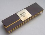
VIC is an acronym for Video Interface Chip and is the collective name for a number of microchips. The VIC controls the graphics routines (chars, sprites, graphic modes) for many computers manufactured by Commodore. The microchips were produced by the semiconductor manufacturer MOS Technology, which Commodore took over in 1976.
VIC-I[edit | edit source]
The VIC-I (cardinality added retrospectively) was designed for Commodore VIC-20 colour video graphics applications such as that required by low cost CRT terminals, biomedical monitors, control systems displays and arcade or home video games. It provides all of the circuitry necessary for generating colour programmable character graphics with high screen resolution. The VIC-I also incorporates sound effects and A/D converters for use in a video game environment. Its features are:
- Fully expandable system with a 16K byte address space.
- System uses industry standard 8 bit wide ROMS and 4 bit wide RAMS
- Mask programmable sync generation (NTSC-6560, PAL-6561)
- On-chip colour generation (16 colours)
- Up to 600 independently programmable and movable background locations on a standard TV.
- Screen centering capability
- Screen grid size up to 192 Horizontal by 200 Vertical dots
- Two selectable graphic character sizes.
- On-chip sound system including:
- White noise generator
- Amplitude modulator
- Two on-chip 8 bit A/D converters
- On-chip DMA and address generation
- No CPU wait states or screen hash during screen refresh
- Interlaced/Non-Interlaced registers
- Light gun/pen for target games
- 2 modes of colour operation
VIC-II[edit | edit source]
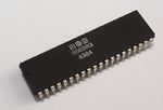
The VIC-II is the microchip tasked with generating Y/C video signals (combined to composite video in the RF modulator) and DRAM refresh signals in the C64 and C128 range of home computers. The VIC-II typically accesses the memory alternately with the CPU. However, it can also freeze the CPU briefly and access the memory with higher bandwidth during that time. This happens in the so-called "Badlines" and is necessary since the bandwidth would otherwise be insufficient. The VIC-II is connected to the Color RAM via a dedicated four bits data bus. Its features are:
- 16 kB address space for screen, character and sprite memory
- 320 × 200 pixels video resolution (160 × 200 in multi-color mode)
- 40 × 25 characters text resolution
- Three character display modes and two bitmap modes
- 16 colors
- Concurrent handling of 8 sprites per scanline, each of 24 × 21 pixels (12 × 21 multicolor)
- Raster interrupt (see details, below)
- Smooth scrolling
- Independent dynamic RAM refresh (an unusual feature for a graphics processor)
- Bus mastering for a 6502-style system bus; CPU and VIC-II accessing the bus during alternating half-clock cycles (the VIC-II will halt the CPU when it needs extra cycles)
Succeeding MOS's original VIC, the VIC-II was one of the two chips mainly responsible for the C64's success; the other microchip being the MOS 6581 SID).
Registers[edit | edit source]
| Hex Address | Dec Address | Page | Contents |
|---|---|---|---|
| $D000-$D3FF | 53248-54271 | Page 208-211 | VIC-II registers |
- Sprites lie at address MEM(Start of screen mem + $03F8 + sprite number)*64
- The start of the Screen RAM (the VIC bank) is set by $DD00 (see CIA 2) and $D018.
VIC-II Technical Details[edit | edit source]
The operation of the VIC-II is thoroughly described in the document "The MOS 6567/6569 video controller (VIC-II) and its application in the Commodore 64" (1996) by Christian Bauer. A slightly more readable timing overview can be found here.
Notes on the document:
- The cycle count starts at 1; for example, VICE starts counting at 0.
- The document refers to ø0; in other sources, Phi1 (ø0 low) and Phi2 (ø0 high) are often mentioned.
- Writing to $D011/$D012 can immediately trigger a raster IRQ, provided no raster IRQ has yet been triggered in the current line.
- The vertical "expansion flip-flop" is somewhat misleadingly named; its state actually indicates whether a line in the sprite data should currently be skipped or not (MCBASE, +3 in two steps: +2 in cycle 15, +1 in cycle 16). For standard-size sprites, this flag is always set. For vertically double-sized sprites, it is cleared in the first line, then alternates each raster line.
- Sprite crunch/sprite stretching by clearing bits in $D017 shifts MC(BASE) in a slightly different manner than stated in the document.[1]
- VCBASE and MCBASE are used to reset VC and MC to their initial values. VCBASE is the offset into the screen memory (in standard text mode: 0 for raster lines 51-58, 40 for raster lines 59-66, and so on), while MCBASE is the offset within the sprite data (0, 3, 6 for standard-size sprites; 0, 0, 3, 3, 6, 6 for vertically double-height sprites).
- VMLI is not a pointer but rather a 40-bit shift register that controls the 40 enable bits of the VIC-II’s internal "40×12 bit video matrix/color line." When switching from idle to display mode, a "1" is shifted into the register and then continues to shift after each C/G access.
- A Badline triggered as early as cycle 15 results in a VSP offset of 1. Presumably, the transition from idle to display mode does not occur on the falling edge of ø0 but rather on the rising edge.[2]
- Example of access timing (in standard text mode) for the second line of the character in the top left corner ($0400):
- The character and its color are determined by the C-access on line 51 (a Badline) in the second half of cycle 15.
- The character pixels displayed are determined by the G-access on line 52 in the first half of cycle 16.
- The background color for the character is determined by the state of $D021 on line 52 at the end of cycle 17.[3]
VIC-III[edit | edit source]
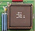
Graphics in the C65 (also known as the C64DX) were to be provided by the VIC-III (designated the CSG 4567, and named as the "Bill" chip for designer Bill Gardei). Its features are:
- Support of standard C64 video modes.
- Textmode with 40/80 × 25 characters (featuring blink, bold, and underline).
- True bitplane VGA-style graphics:
- 320x200x256
- 640x200x256
- 640x400x16
- 1280x200x16
- 1280x400x4
- Palette of 4096 colours.
- Special facility for address resolution (Display Address Translator [DAT]) of the C64 pixel coordinate system.
- PAL only, no NTSC (but the RGB output works just fine with the 1084S).
- Synchronizable with external video source (Genlock).
- Integrated DMA-Controller (Bit blit).
- Reportedly can display Amiga OCS IFF.
Microprocessor Identification[edit | edit source]
- MOS Technology 6560 – VIC-I for (NTSC) VIC-20
- MOS Technology 6561 – VIC-I for (PAL) VIC-20. Revision: -101/E
- MOS Technology 6564 – VIC-I for Colour PET
- MOS Technology 6566 – VIC-II for MAX Machine
- MOS Technology 6567 – VIC-II for (NTSC) C64, SX-64, PET 64, C64GS. Revision: R56A/R7/R8/R9
- MOS Technology 6569 – VIC-II for (PAL) C64, SX-64, PET 64, C64GS, MAX Machine. Revision: R1/R3/R4/R5 (R1 = only 5 lumas)
- MOS Technology 6572 – VIC-II (PAL-N)
- MOS Technology 6573 – VIC-II (PAL-M)
- MOS Technology 8562 – VIC-II (NTSC)
- MOS Technology 8564 – VIC-II for (NTSC) C128, C128D, C128DCR
- MOS Technology 8565 – VIC-II for (PAL-B) C64. Revision: R2
- MOS Technology 8566 – VIC-II for (PAL-B) C128, C128D, C128DCR
- MOS Technology 8569 – VIC-II for (PAL-N) C128, C128D, C128DCR
Notes
- The NMOS variants 6566/67/69 require +12V on Pin 13/Vdd; the HMOS-II variants (8562/65) require only +5V DC.
- The 856x variants exhibit the Grey Dots problem.
References[edit | edit source]
- ↑ See Sprite Crunch handling code in VICE.
- ↑ x64sc in VICE performs the G access first in
vicii-cycle.c/vicii_cycle(), then checks for a badline condition incheck_badline()and switches to Display Mode if necessary. Kawari checks for a badline condition first [1] but doesn't change the mode, then increments VC in the next half cycle (if in Display Mode), then switches from Idle to Display Mode (on a badline condition) [2]. - ↑ See the 12 pixel delay remark in section 3.6.1. of the VIC article.
Hardware internals of the C64 · Hardware portal
Components of the C64: CPU · VIC · SID · CIA · PLA · RAM · ROM · Color RAM


