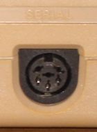
Serial Port

The serial bus (IEC or CBM bus) is the standard interface for connecting external devices as disk drives or printers. Technically, it is a commodore-specific variant of the parallel IEEE-488/IEC-625-Bus, therefore it is often called IEC bus or CBM bus. This interface variant is not compatible with RS232, which is the standard for the serial interface for IBM-compatible PCs.
Since serial ports are usually used only for the connection of two devices (e.g. RS232) the IEC bus is a serial bus. More than only one device can be connected, therefore most of the peripheral devices have loop-through connectors. Theoretically there are up to 31 devices possible (device numbers 0 to 30, 31 is reserved for UNTALK/UNLISTEN). However, the operating system of the C64 can use only the device numbers 4 to 30, because 0-3 are already used internally. Practically the upper limit is at around 8 devices. The reason for this is, that the chips (inverting driver 7406) in the C64 can handle a maximum load current of 40 mA. And any device, which is connected to the serial bus draws 5mA. However, nothing prevents a single physical device from responding to more than one address.
The selection, with which device data will be exchanged, will be done with the device number. This number between 4 and 30 must be selected on the device and must be unique. Standard for printers is 4, for the first floppy drive 8.
The timing of the bus is specified quite tightly. So if a PC is connected with an appropriate cable (see X1541) to a floppy drive and is transmitting data - or vice versa (i.e. the PC emulates a floppy for a C64) everything may work fine. But if you use a multitasking OS (Windows, Linux,...) it will not work without using a complex circuit with own intelligence because of the maximum allowed latency of only a few micro seconds (especially when using a fast loader). For this reason software as 64HDD and 1541EMU are running under DOS only.
In standard operation (LOAD, unmodified KERNAL-routines) the serial bus is capable to transmit 400 byte/second using a 1541 and approx. 650 bytes/second using an SD2IEC. With JiffyDOS and a 1541 approx. 2.4 kbyte/second are transmitted while JiffyDOS and a SD2IEC achieve 8.6 kbyte/second. The theoretic maximum is at about 20-25 kbyte/second[1].
Pin assignment[edit | edit source]
The serial interface is a 6-pin DIN connector (DIN 45322).

| Pin | Description | Signal direction | Remark |
|---|---|---|---|
| 1 | SERIAL SRQ | IN | Serial Service Request In, at the C128 "Fast Serial Clock" |
| 2 | GND | - | Ground, signal ground (0V) |
| 3 | SERIAL ATN | OUT | Attention, for the selection of a device at beginning/end of a transmission |
| 4 | SERIAL CLK | IN/OUT | Clock (for data transmission) |
| 5 | SERIAL DATA | IN/OUT | Data |
| 6 | SERIAL RESET | OUT(/IN) | Reset, in older VIC-20 unused |
Signal description[edit | edit source]
- Attention: a lot of fast loaders use these signals differently! The here described pin assignment is valid only for the standard usage of the bus.
- All signals (except from GND) are LOW-active. If they are inactive they are on a voltage level of about 5V (HIGH).
- Electrically, all signals are open collector, to keep the bus behaviour.
SRQ: Serial Service Request in
Any device can draw this signal to LOW, to request data exchange with the computer. The C64 does not use this signal, but it is connected with the read line of the cassette port (although this can only detect signal edges, but not signal levels).
The C128 uses this line as "Fast Serial Clock" for the 1571/1581 disk drive.
ATN: Serial Attention out
If this signal is LOW and a byte is sent, all connected devices on the bus are interpreting this as a command. As soon as the C64 draws ATN to LOW, all other devices are waiting for the transmission of the address (device number). The addressed device has to answer within a defined time frame, else the C64 assumes, that this device is not present and gives an error message. After the device number the secondary address will be sent, ATN stays LOW. Before the first "normal" byte it will go back to HIGH state.
CLK: Serial Clock in/out
This signal is the clock of the transmitted data. The clock will be generated by the device which sends the data. At the rising edge of CLK, the receiver takes over the actual DATA bit.
DATA: Serial Data in/out
The data will be transferred via this line sequentially bit by bit. A byte transmission starts with bit 0 LSB and ends with bit 7 MSB for the standard protocol, or the reverse for the fast protocol.
RESET: Serial Reset
This generates a reset at the connected devices. Early models of the C64 allowed to use it as input to reset the computer (Reset-button), at later models this is not possible any more. Therefore a reset-button switch should be connected to the user port.
Expansions[edit | edit source]
- It is possible to increase the number of physically connected devices on the bus. To do this in some of the devices the 1kΩ resistors must be removed. Attention: If they will be removed in all devices, the bus will not work any more.
- Power over Serial Voltage for low consumption devices.
Links[edit | edit source]
| Wikipedia: CBM-Bus |
- Book Die Floppy 1541 including notes on the serial bus

- IEC disected, in-depth details to the IEC-protocol, 2008, compiled by J. Derogee

- HOW THE VIC/64 SERIAL BUS WORKS, (short) article from the Compute! July 1983 by Jim Butterfield

- C64-Netzwerk mit dem seriellen Bus, Networking via the serial bus
