SID
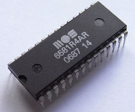
SID (short for Sound Interface Device) is the name of the sound chip used in the VC 10, C64 and C128. The SID was developed by Bob Yannes, an employee of the firm MOS Technology. Bob (Robert) Yannes knows, beside technical know-how, a lot of music. His intention was to implement a real subtractive synthesis chip, totally different from all other home computer sound devices of its time. The chip's distinctive sound is easily recognized and was clearly ahead of the competition. The chip combines analogue and digital circuitry, that cannot be emulated with 100% fidelity even today. Emulated sounds do come very close to the original and a layperson is not likely to notice the difference. The SID sound is well known among retro gamers.
The Commodore 64 & Commodore 128 & 128D (plastic case) use the 6581 chip. The Commodore 64-II and Commodore 128DCR (metal case) use the newer 8580 chip. There are also new chip replacements that emulate the SID like SIDKick pico or SwinSID. The SID can be programmed in BASIC or machine language using a machine language monitor or an Assembler package (e.g. Merlin, Commodore Assembler, etc.).
A collection of SID music is available that includes nearly every song ever written for the chip and is known as the High Voltage SID Collection. This collection can be heard on modern computers using utilities such as SIDPLAY.
Properties of the SID[edit | edit source]
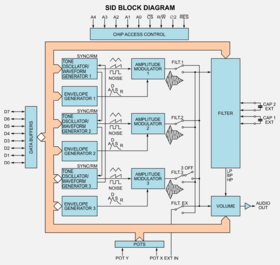
- 3 tone generators (voices), frequency 0-4 kHz (16 Bit decomposition)
- 4 forms of waves (sawtooth, triangle, rectangle pulse width modulation, (white) noise /rush)
- 3 amplitude modulator, until 48 dB
- 3 envelope generators
- Synchronization of the oscillators
- Ring modulation
- Programmable filters (low pass, bandpass, high pass)
- Master volume in 16 steps
- 2 A/D-converter (8 bit, low frequency, used for reading paddle input)
- Random generator
- Audio input (cannot be used for sampling, but the signal can be routed through the SID filter)
Chip variations[edit | edit source]
| Chip | Production period | Remark |
|---|---|---|
| 6581 | 21/1982 - 30/1985 | NMOS, pin 28/Vdd = 12V DC, each 470pF on pins 1+2/3+4 |
| 6581R3 | 42/1985 - 07/1986 | |
| 6581R4 | 16/1986 - 30/1986 | |
| 6581R4AR | 22/1986 - 06/1987 | |
| 8580R5 | 06/1987 - 19/1992 | HMOS-II, pin 28/Vdd = 9V DC, each 22nF on pins 1+2/3+4, digisound without digifix very quiet. |
Info: The checked production period based on a limit number of SID chips. A larger production period is most likely!
Memory Addresses of the SID[edit | edit source]
| address (decimal) | function | |||||||
|---|---|---|---|---|---|---|---|---|
| $d400 (54272) | frequency voice 1 low byte | |||||||
| $d401 (54273) | frequency voice 1 high byte | |||||||
| $d402 (54274) | pulse wave duty cycle voice 1 low byte | |||||||
| 7..4 | 3..0 | |||||||
| $d403 (54275) | — | pulse wave duty cycle voice 1 high byte | ||||||
| $d404 (54276) | control register voice 1 | |||||||
| 7 | 6 | 5 | 4 | 3 | 2 | 1 | 0 | |
| noise | pulse | sawtooth | triangle | test | ring modulation with voice 3 | synchronize with voice 3 | gate | |
| 7..4 | 3..0 | |||||||
| $d405 (54277) | attack duration | decay duration voice 1 | ||||||
| $d406 (54278) | sustain level | release duration | ||||||
| $d407 (54279) | frequency voice 2 low byte | |||||||
| $d408 (54280) | frequency voice 2 high byte | |||||||
| $d409 (54281) | pulse wave duty cycle voice 2 low byte | |||||||
| 7..4 | 3..0 | |||||||
| $d40a (54282) | — | pulse wave duty cycle voice 2 high byte | ||||||
| $d40b (54283) | control register voice 2 | |||||||
| 7 | 6 | 5 | 4 | 3 | 2 | 1 | 0 | |
| noise | pulse | sawtooth | triangle | test | ring modulation with voice 1 | synchronize with voice 1 | gate | |
| 7..4 | 3..0 | |||||||
| $d40c (54284) | attack duration | decay duration voice 2 | ||||||
| $d40d (54285) | sustain level | release duration voice 2 | ||||||
| $d40e (54286) | frequency voice 3 low byte | |||||||
| $d40f (54287) | frequency voice 3 high byte | |||||||
| $d410 (54288) | pulse wave duty cycle voice 3 low byte | |||||||
| 7..4 | 3..0 | |||||||
| $d411 (54289) | — | pulse wave duty cycle voice 3 high byte | ||||||
| $d412 (54290) | control register voice 3 | |||||||
| 7 | 6 | 5 | 4 | 3 | 2 | 1 | 0 | |
| noise | pulse | sawtooth | triangle | test | ring modulation with voice 2 | synchronize with voice 2 | gate | |
| 7..4 | 3..0 | |||||||
| $d413 (54291) | attack duration | decay duration voice 3 | ||||||
| $d414 (54292) | sustain level | release duration voice 3 | ||||||
| $d415 (54293) | — | filter cutoff frequency low byte | ||||||
| $d416 (54294) | filter cutoff frequency high byte | |||||||
| $d417 (54295) | filter resonance and routing | |||||||
| 7..4 | 3 | 2 | 1 | 0 | ||||
| filter resonance | external input | voice 3 | voice 2 | voice 1 | ||||
| $d418 (54296) | filter mode and main volume control | |||||||
| 7 | 6 | 5 | 4 | 3..0 | ||||
| mute voice 3 | high pass | band pass | low pass | main volume | ||||
| $d419 (54297) | paddle x value (read only) | |||||||
| $d41a (54298) | paddle y value (read only) | |||||||
| $d41b (54299) | oscillator voice 3 (read only) | |||||||
| $d41c (54300) | envelope voice 3 (read only) | |||||||
| $d500..$d7ff (54528-55295) | SID registers mirrored (not in C128) | |||||||
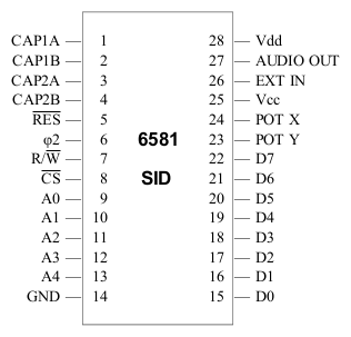
Pinout[edit | edit source]
Programming in BASIC[edit | edit source]
A small BASIC program for the C64 demonstrates some sound effects. Only the first voice of the SID is used for this. The program can only be interrupted with the RUN/STOP key.
 0 REM *** C64-WIKI SOUND-DEMO ***
10 S = 54272: W = 17: ON INT(RND(TI)*4)+1 GOTO 12,13,14,15
12 W = 33: GOTO 15
13 W = 65: GOTO 15
14 W = 129
15 POKE S+24,15: POKE S+5,97: POKE S+6,200: POKE S+4,W
16 FOR X = 0 TO 255 STEP (RND(TI)*15)+1
17 POKE S,X :POKE S+1,255-X
18 FOR Y = 0 TO 33: NEXT Y,X
19 FOR X = 0 TO 200: NEXT: POKE S+24,0
20 FOR X = 0 TO 100: NEXT: GOTO 10
21 REM *** ABORT ONLY WITH RUN/STOP ! ***
Because of the many controls of the SID, the SID's base address should be put into a variable, i.e. S = 54272. Before the waveform (here: register 4) is used, the envelope (ADSR; here: register 5 and 6) should be set. The volume (register 24) can only be set for all voices at once.
Trivia[edit | edit source]
Bob Yannes later went on to form the well known synthesizer company Ensoniq. Their first synthesizer, the ESQ-1 is, according to Bob, the synthesizer he wanted the SID chip to be. Due to a rough time table, a lot of features had to be dropped and the design was finished just in time. Many characteristics of the SID sound are bugs, technically seen, but depending on the point of the listener they can be seen as features or were used to hack the chip. For example the volume register design flaw in the original 6581 chip was used to play back samples. Every time the volume register value was altered, an audible click could be heard. By changing the first 4 bits of the register at $D418 fast enough, samples can be played back with rates up to some kHz (depends on the code and what else uses rastertime) with 4 bit resolution. In the later 8580 model this "bug" was fixed and samples were inaudible, but it is possible to revert this by soldering a 470kΩ resistor or, if you want to be able to adjust the level, a 1MΩ pot in series between EXT IN and GND. Even better sample playback can be achieved by altering the pulse width modulation register, which can hold an eight bit value.
Troubleshooting[edit | edit source]
- If there is no audio on pin 3 of the A/V jack then it's possible that the 9VDC supply is missing, which is one cause of this
- If paddles aren't working properly a defective SID may be the reason for this
Links[edit | edit source]
| Wikipedia: MOS_Technology_SID |
- The SID in the Commodore Computer Online Museum

- MOS 6581 SID data sheet (PDF Format)
- MOS 6582 SID data sheet (PDF Format)
- Windows program to manage the HVSC
- Die shots of VIC II 6569 and SID 6581, 8580
 from Michael Huth
 - SID in-depth information site
 from Darius Kubarth
Hardware internals of the C64 · Hardware portal
Components of the C64: CPU · VIC · SID · CIA · PLA · RAM · ROM · Color RAM


