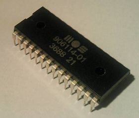
PLA (C64 chip)
The Programmable Logic Array (PLA) is a hardware programmable chip in the C64 which only contains combinatorial logic.
Designed by Dave DiOrio, the PLA is used to create chip select signals received from various other signals. These signals control which chip is to be connected to the data bus. Therefore the PLA is responsible for dictating the memory map of the C64 and enables the implementation of bank switching. Commodore engineer James Redfield said it was the "glue logic to tie everything together". The final version of the PLA logic was REV3.
This chip is failure prone, especially the earliest models. Eventually, the third party PLAs were created, such as the SuperPLA, realPLA, U17 PLAnkton, PLAtinum, neatPLA, PLA20V8 (aka "GAL-PLA") and also PLAs based on eproms as a replacement part.
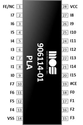
Pinout[edit | edit source]
| Pin | Name | Remarks |
|---|---|---|
| 1 | FE/NC | Used for programming field-programmable parts and not connected internally for mask programmable parts.[1] |
| 2 | I7 | Connected to A13 of the address bus |
| 3 | I6 | Connected to A14 of the address bus |
| 4 | I5 | Connected to A15 of the address bus |
| 5 | I4 | Connected to #VA14 on VIC-II |
| 6 | I3 | Connected to #CHAREN on I/O port of the 6510 CPU |
| 7 | I2 | Connected to #HIRAM on I/O port of the 6510 CPU |
| 8 | I1 | Connected to #LORAM on I/O port of the 6510 CPU |
| 9 | I0 | Connected to #CAS on the VIC-II |
| 10 | F7 | #ROMH |
| 11 | F6 | #ROML |
| 12 | F5 | #I/O |
| 13 | F4 | GR/#W, connected to #WE on the color RAM |
| 14 | VSS | GND |
| 15 | F3 | Connected to #CS1 on the #CHAROM |
| 16 | F2 | Connected to #CS on the #KERNAL ROM |
| 17 | F1 | Connected to #CS on the #BASIC ROM |
| 18 | F0 | #CASRAM, connected to the #CAS pin on the DRAM |
| 19 | #CE | Chip Enable |
| 20 | I15 | Connected to VA12 on VIC-II |
| 21 | I14 | Connected to VA13 on VIC-II |
| 22 | I13 | Connected to #GAME on pin 8 of cartridge port |
| 23 | I12 | Connected #EXROM on pin 9 of cartridge port |
| 24 | I11 | Connected to R/#W of the bus |
| 25 | I10 | #AEC, connected to inverted version of AEC on the VIC-II |
| 26 | I9 | Connected to BA on the VIC-II |
| 27 | I8 | Connected to A12 of the address bus |
| 28 | VCC | +5V |
Links[edit | edit source]
- Giesel, Thomas: "The C64 PLA Dissected"; accessed 24 October 2013
- pla.txt
 - PLA circuit logic for old 82S100-PLAs at zimmers.net
 - PLA signal matrix
- PLA signal matrix explanation from The Transactor Volume 6, Issue 05, pp. 51,

